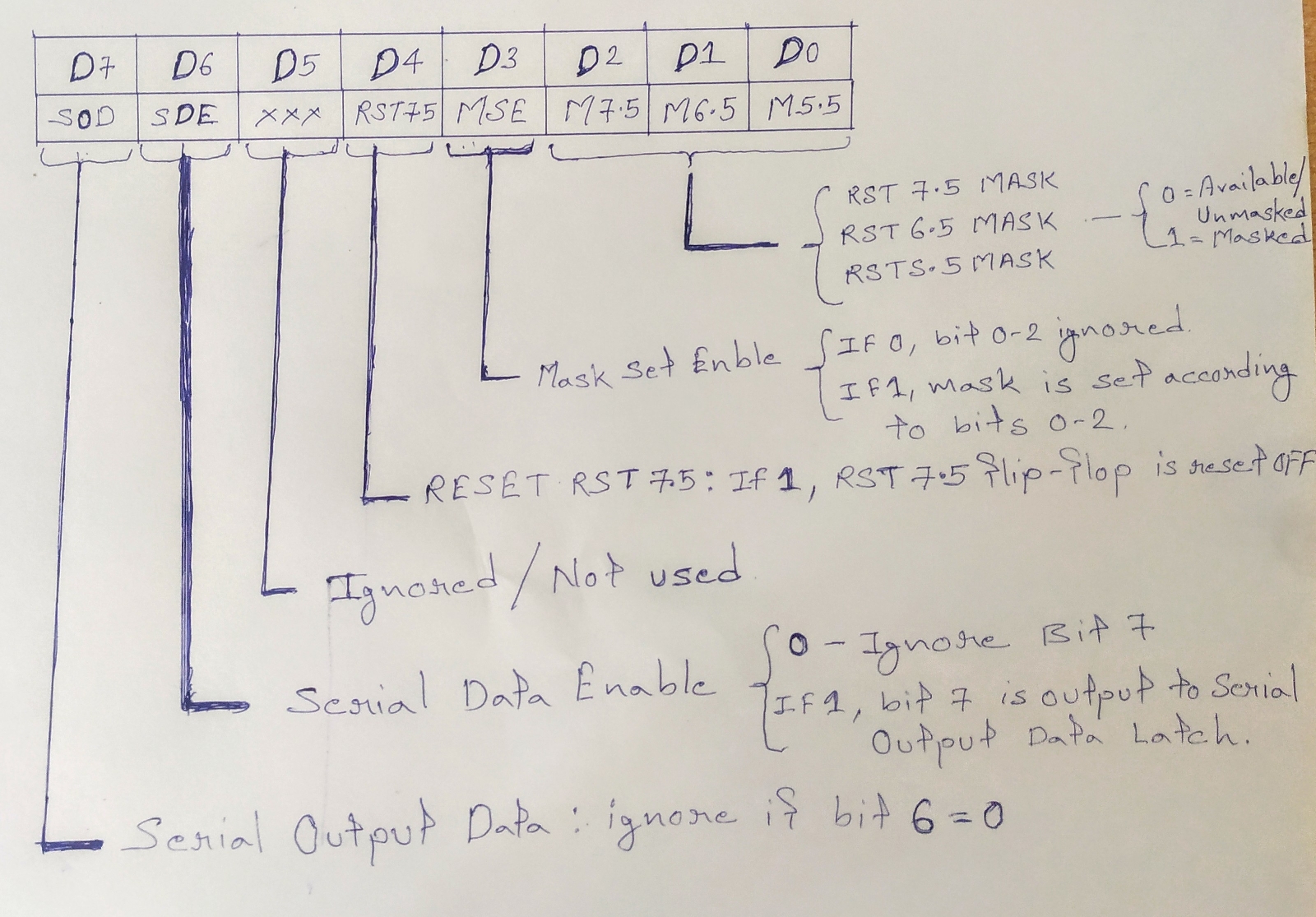
Set Interrupt Mask (SIM) instruction Set Interrupt Mask (SIM) – It is used to implement the hardware interrupts (RST 7.5, RST 6.5, RST 5.5) by setting various bits to form masks or generate output data via the Serial Output Data (SOD) line. First the required value is loaded in accumulator then SIM will take the bit pattern from it. Instruction SIM: Set Interrupt Mask. This is a 1-byte instruction and can be used for three different functions. one function is set mask for RST 7.5, RST 6.5 and RST 5.5 interrupts. This instruction reads the content of the accumulator and enables or disables the interrupts according to the content of the accumulator. Bit D3 is a control bit and should =1 for bit D0, D1 and D2 to be effective. Logic 0 on D0, D1, and D2 will enable the corresponding interrupts, and logic 1 will disable the interrupts. The second function is to reset RST 7.5 flip-flop. Bit D4 is additional control for RST 7.5. If D4=1, RST 7.5 reset. This is used to ove...