Generation of Control Signals of 8085
Generation of Control Signals
In any system, there are different
modes of operations. Likewise, in some situation we are interested to read data
in microprocessor, in other we are interested to write data on some location
from microprocessor. Whenever, we are dealing with different peripherals using
8085 microprocessor there are two modes of operations. One is to read data from
any of the memory device or input device. Second is to write data on some
location, this location can be any of the output device location or any of the
memory location. To deal with these modes 8085 microprocessor architecture gives
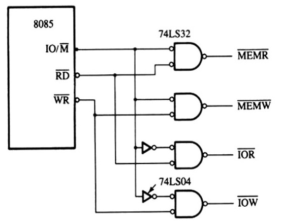
three different control signals. Namely IO/M,RD and WR. The IO/M is an output pin of the
8085 microprocessor which serves dual purpose, the high going pulse on this pin
indicates the I/O type of operation. We can state that, at this time 8085 is
working with the input or output devices. The low going pulse on this pin
indicates the memory operation. The second one is the RD stand for read signal.
This is active low signal, indicates the memory or I/O type of read operation
and the selected memory or I/O device is to be read. And the third is WR stands for write
signal. This is also active low signal, indicates the memory or I/O type of
write operation and data available on the Data bus is to be written in to the
selected memory or I/O location, data is set up at the trailing edge of the
pin. To deal with different I/O as well as memory device individually, we have
to generate four individual control signals. This control signals used to
select any of the I/O or memory device, with a specific type of operation
either of read or write. In our case, we are interested with two operation with
memory as well as output devices. First of all, we required to fetch the
instructions place inside the memory and next we write data word on output
port. According to our need we have develop the logic to generate control
signals. The figure describe
the combination logic of signal generation.
Figure: - Example of the schematic
Diagram to generate control signals
Figure: - The combination of control signals as well as de-multiplexing the bus system
REFERENCES
- R. S. Gaonkar, Microprocessor
Architecture, Programming, and Applications with the 8085, Fifth Edition,
Penram International Publishing (India) Private Limited.
- S Ghoshal, Microprocessor Based
System Design, Macmillan India Limited, 1996
- M. Mano, Digital Logic and
Computer Design, Prentice – Hall India
- B.
Ram - Fundamentals of Microprocessor and Microcontrollers
- “Microprocessors: Principles
and Applications” by A Pal
- “Microprocessors and
Microcontrollers : Architecture, Programming and Interfacing Using 8085,
8086 and 8051” by Soumitra Kumar Mandal
- “Introduction to
Microprocessors and Microcontrollers” by Crisp John Crisp
- “Microprocessors And
Microcontrollers” by A Nagoor Kani
- “Microprocessors And
Microcontrollers : Architecture, Programming and System Design 8085, 8086,
8051, 8096” by KRISHNA KANT
- “8 - Bit
Microprocessor”
by Vibhute


Comments
Post a Comment